Introduction: The Quest for the Perfect Portable Delta Loop Antenna
For the modern amateur radio operator, the allure of portable operation is undeniable. The quest for a high-performance antenna that is easy to deploy in the field often leads to compromise. This guide provides the solution: a complete plan to build the AH6CY portable 4-band delta loop. Whether activating a park for POTA or setting up for Field Day, this project moves beyond inefficient verticals and shortened dipoles. It’s time to build a portable antenna that pulls in weak DX signals with authority, without the typical trade-offs in size and performance.
What if there was a portable antenna that didn’t compromise? An antenna that was not only easy to deploy but was a top-tier performer, capable of pulling in weak DX signals with authority? For decades, the full-wave delta loop has been a legendary performer at home stations, known for its impressive gain and quiet reception. However, its size has often kept it out of the portable operator’s toolkit.
That is, until now. Enter the brilliant and practical design of Hiroki Kato, AH6CY, a respected ham and prolific antenna innovator whose work has been featured in premier publications like RadCom and QST. Hiroki has developed and perfected a portable 4-band delta loop that leverages modern materials to make this high-performance antenna a reality for field operations. This article is your definitive guide to building this exceptional antenna. We will unpack its design, explore its significant performance advantages, and provide a complete, step-by-step plan for you to build a DX-capable, multi-band powerhouse for your next portable adventure.

Why a Delta Loop? Unpacking the Performance Advantages
Before diving into the build, it is essential to understand why this project is so worthwhile. The delta loop is not just another field antenna; its fundamental design offers distinct, measurable advantages over the dipoles and verticals that dominate the portable landscape. By investing a little time in this homebrew portable 4-band delta loop, you are building an antenna that is engineered to outperform many commercial options.
Surprising Gain and a Low Angle of Radiation
The most significant advantage of a full-wave loop is its inherent gain. A delta loop is not simply a bent dipole; it functions more like two stacked, in-phase dipoles, which provides real, measurable gain over a standard half-wave dipole or a quarter-wave vertical. This gain is your “power amplifier in the sky,” making your QRP signal sound stronger and helping you hear stations that would be lost in the noise on a lesser antenna. Furthermore, when erected vertically, the delta loop is a DX powerhouse. It concentrates its radiated energy at a low takeoff angle, firing your signal toward the horizon rather than up into the clouds. This low angle is critical for long-distance (DX) communication, as it promotes multi-hop skywave propagation. For the 20-meter element on this antenna, operating on the 10-meter band provides an even greater advantage, functioning like four stacked dipoles.
The “Magic” of a Quiet Antenna
One of the biggest challenges in modern radio, especially in portable locations near urban centers, is radio frequency interference (RFI), often referred to as QRM (man-made noise) and QRN (natural noise). Verticals, in particular, are notoriously susceptible to picking up local noise from power lines, appliances, and digital devices. The delta loop, as a closed-loop antenna, is inherently balanced and less susceptible to picking up this vertically polarized, common-mode noise. The result is a dramatically lower noise floor. This is a game-changing advantage. A quieter antenna allows you to hear weak signals that would otherwise be completely buried in the noise, giving you a distinct edge in crowded band conditions or when chasing rare DX.
Ditch the Radials! The Ultimate Portable Convenience
Ask any portable operator about their least favorite part of setting up a vertical antenna, and the answer is almost always the same: the radials. Laying out, tuning, and untangling a field of quarter-wave radials is time-consuming, takes up a large footprint, and can be a tripping hazard. The full-wave delta loop completely eliminates this requirement. As a self-contained, full-wavelength antenna, it does not require a ground plane or radial system to operate efficiently. This translates to a dramatically faster setup and teardown time, a much smaller operational footprint, and less gear to carry—three factors that are paramount for successful and enjoyable portable operations.
Naturally Broadbanded Performance
Many portable antennas are notoriously finicky, requiring precise tuning with an antenna tuner for even small frequency changes. The delta loop, due to its full-wave nature, is naturally more broadbanded. Once constructed to the proper dimensions, this design exhibits a very low Voltage Standing Wave Ratio (VSWR) across large segments of the 20, 17, 15, and 10-meter bands. For many operators, this means you can change bands and operate across the phone and digital portions without ever needing to touch an antenna tuner, simplifying your station and getting you on the air faster.
About the Designer: Hiroki Kato, AH6CY
A great design is often born from the passion and experience of its creator. Hiroki Kato, AH6CY, is a testament to this. With a compelling personal history rooted in Hiroshima, Japan, his fascination with radio has been a lifelong journey. Now an active operator in California, Hiroki is a dedicated antenna experimenter and a key member of the vibrant QRPops (QRP operators) group, which meets weekly to test and compare home-brewed and commercial antennas in real-world conditions.
His approach is practical, performance-driven, and born from countless hours of on-air testing. This portable 4-band delta loop is not a theoretical design; it is the result of rigorous experimentation aimed at solving the real-world challenges faced by portable operators. By building this antenna, you are benefiting from the expertise and community spirit that Hiroki embodies. For those interested in learning more about his fascinating story and his contributions to the hobby, his in-depth interview on the QSO Today podcast is highly recommended.
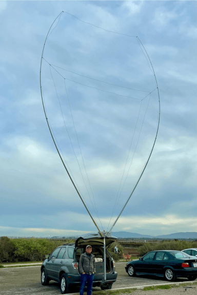
The AH6CY Portable 4-Band Delta Loop: A Masterclass in Design
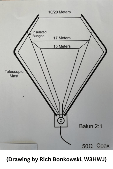
Originally published in the prestigious RadCom magazine of the Radio Society of Great Britain (RSGB), Hiroki’s design is a masterclass in elegant simplicity and effectiveness. The core innovation is the use of two tall, lightweight, telescopic fiberglass masts. Instead of requiring a rigid frame, the design cleverly uses the natural, gentle arc of the extended masts to provide the necessary shape and tension for the three nested delta loop wire elements. This creates a large, efficient, multi-band aperture that is both incredibly lightweight and quick to deploy.
To help you get started, we are pleased to provide Hiroki’s original design document. This PDF contains his diagrams, construction notes, and performance data.
Download the complete, original design document from Hiroki Kato, AH6CY, as published in RadCom.
Your Weekend Project: Building the Portable 4-Band Delta Loop
Building the AH6CY delta loop is a rewarding project that is well within the reach of any ham comfortable with basic tools and soldering. Follow these steps to create your own high-performance portable antenna.
The Bill of Materials: Gathering Your Components
Sourcing the right parts is the first step to a successful build. This design uses readily available components. The most critical elements are the non-conductive fiberglass masts, which provide the essential structure and support.
| Component | Specification / Details | Where to Find (Example) | Notes |
| Telescopic Masts | 2x Fiberglass, ~30 ft (8.2m+) | (Antenna Mast (31 ft.) by Jackite) | Crucial: Avoid carbon fiber poles as they are conductive and will detune the antenna. The Jackite poles are lightweight, strong, and ideal for this application. |
| Antenna Wire | 16 AWG stranded, insulated copper | Your local electronics store or online | Total length needed is ~53 meters (175 ft) to be safe. |
| 2:1 Balun | Homebrew or Commercial | See Balun Construction section below | Matches the loop’s ~100Ω impedance to your 50Ω coax. |
| Toroid Core | T130-2 Powdered Iron Core | Online amateur radio parts suppliers | For winding the 2:1 balun. |
| Magnet Wire | 18 AWG Enameled Copper Wire | Online amateur radio parts suppliers | For winding the 2:1 balun. |
| Coax Cable | 50-ohm (e.g., RG-8X, RG-58) | Your preferred radio supply store | Length as needed to reach your rig. |
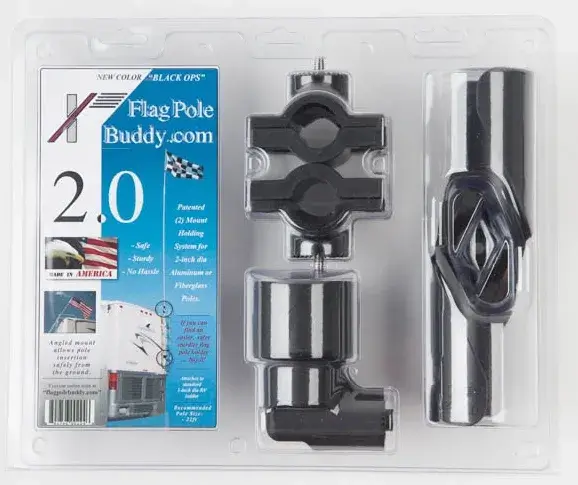
| Hardware | U-bolts, bungee cords, plastic carabiners | Your local hardware store | For rigging the wires and mounting the masts. |
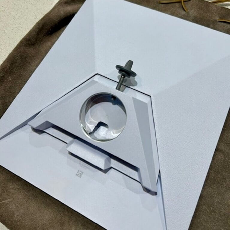
| Mast Mount | Hitch mount, drive-on mount, or custom plate | Hitched4Fun.com Mounts – Individual modifications required. | The design requires a base to hold both masts at a ~70∘ angle. |
Step 1: Preparing the Wire Elements
Precision is key to antenna performance. Carefully measure and cut your three wire elements according to the lengths specified by Hiroki. A pro-tip from experienced builders: always cut your wires a little long. It is much easier to trim a few inches to achieve resonance than it is to splice and add wire back on.
| Band | Wire Length (Meters) | Wire Length (Feet & Inches) |
| 20m / 10m | 21.5 m | 70′ 6.5″ |
| 17m | 16.9 m | 55′ 5.4″ |
| 15m | 14.4 m | 47′ 3″ |
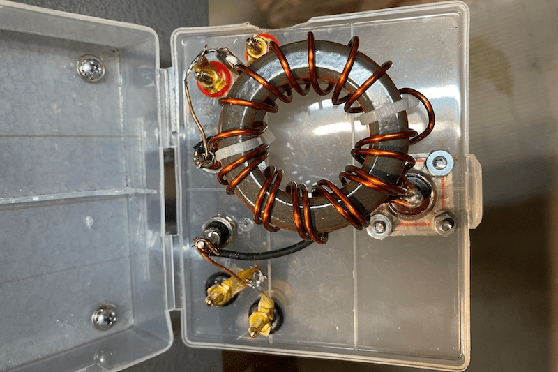
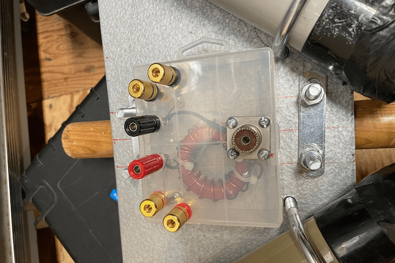
Step 2: Building the 2:1 Balun
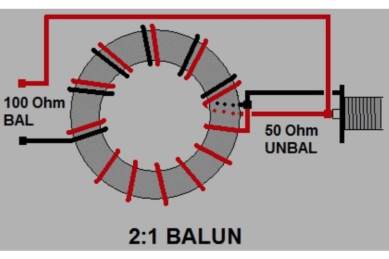
A balun (BALanced to UNbalanced) is a critical component that serves two purposes: it adapts the antenna’s impedance and it prevents the coax shield from radiating, which can cause RFI and distort the antenna’s radiation pattern. A delta loop’s natural feedpoint impedance is around 100−120Ω. To match this to the 50Ω coax and radio your system uses, a 2:1 balun is required.
You can build one easily using a T130-2 toroid core and 18 AWG magnet wire, as detailed in Hiroki’s diagram. The process involves winding the wire through the toroid in a specific way to create an impedance transformer. The balun should be housed in a small, weatherproof plastic case for durability in the field.
Step 3: Assembling the Support Structure
The mechanical genius of this design lies in its support structure. The two fiberglass masts must be mounted to a base plate or bracket that holds them securely at an approximate 70∘ angle to each other. This can be achieved by fashioning a metal plate with U-bolts. For portable operators, an even better solution is to adapt a sturdy vehicle accessory, such as a repurposed bicycle rack or a purpose-built trailer hitch mount, which provides an exceptionally stable and repeatable foundation for the masts. Using a hitch mount on a vehicle provides an instant, robust base without the need for stakes or guying in many conditions. The lightweight nature of the Jackite fiberglass masts makes this type of vehicle-mounted setup incredibly easy to handle by a single person.
Step 4: Rigging and Raising the Antenna
With the masts secured in their base, extend them to their full height. Now, you can rig the wire elements. The longest wire (20m) forms the outermost loop, with the 17m and 15m wires nested inside. Attach the wires to the masts using a combination of bungee cords and plastic carabiners. This system is both simple and effective. The natural, gentle bend of the extended fiberglass masts provides what Hiroki calls the “Goldilock” tension—just enough to keep the wires taut and properly shaped without putting excessive strain on the masts or connection points. The feedpoint, where you connect the 2:1 balun, is located at the bottom center of the loops.
On-the-Air: Real-World Performance
Ultimately, the true test of any antenna is its on-air performance, and this is where the AH6CY delta loop truly shines. The design is not just theoretically sound; in fact, it is a proven, exceptional performer in the field.
VSWR Performance
The broadband nature of the antenna is evident in its VSWR curves. The following table, derived from Hiroki’s measurements, shows that the antenna presents an excellent match to a 50Ω system across the most popular portions of four major DX bands, often eliminating the need for a tuner.
| Band | Center Frequency | VSWR | Bandwidth Notes |
| 20m | 14.250 MHz | 1.1:1 | Under 2.5:1 for the entire band |
| 17m | 18.130 MHz | 1.7:1 | Under 2.0:1 for the entire band |
| 15m | 21.300 MHz | 2.0:1 | Under 3.0:1 for the entire band |
| 10m | 28.400 MHz | 1.2:1 | Under 2.5:1 from 28.0-28.5 MHz |
Export to Sheets
DX Results with QRP
The combination of gain, low noise, and a low angle of radiation translates directly into on-air success. Using this antenna with a low-power (QRP) 10-watt transceiver, Hiroki has routinely worked stations all over North America, as well as DX stations in Japan (JAs) and South America on both SSB and CW. These are not just occasional lucky contacts; they are consistent, repeatable results that demonstrate the antenna’s competitive performance.
Perhaps the most compelling evidence comes from the side-by-side comparisons conducted at the weekly QRPops group meetups. When tested against a variety of popular commercial and homebrew portable antennas—including verticals, end-fed half-waves (EFHWs), and magnetic loops—Hiroki’s delta loop has consistently outperformed them all for DX contacts. This is powerful social proof that this antenna is a superior choice for the serious portable operator.
Get Started on Your Delta Loop & See You at Pacificon!
Building your own antenna is one of the most rewarding activities in amateur radio. With this guide and Hiroki Kato’s brilliant design, you can construct a portable 4-band delta loop that will outperform many commercial antennas, elevate your portable operations, and give you a powerful new tool for chasing DX. It’s a project that delivers immense satisfaction and a truly competitive signal from the field.
To make things even more exciting, this antenna will be a featured topic at an upcoming major ham radio event. Hiroki Kato, AH6CY, will be presenting his “Homebrewing Portable HF Antennas” seminar at the upcoming Pacificon 2025 convention in San Ramon, CA, where he will be diving deep into this very 4-band delta loop design.
We’ll be there too! Stop by the Hitched4Fun.com vendor booth to see the 31 ft. Jackite Fiberglass Masts in person. We would love to chat about your project, answer your questions, and help you get the core components you need to build your own high-performance portable station. We look forward to seeing you there and hearing you on the air!